
DIY - Hướng dẫn tự làm công tắc WiFi điều khiển từ xa cho bạn
DIY - Hướng dẫn tự làm công tắc WiFi điều khiển từ xa cho bạn

Video hướng dẫn tự làm công tắc WiFi điều khiển từ xa cho nhà bạn dựa trên nền tảng IoT LOTODA platform
Bạn dễ dàng kết nối đến LOTODA platform bằng Board ESP8266 kit, để tạo một dự án bật/tắc công tắc từ xa! Hãy download code tại đây và sử dụng Arduno IDE để nạp code!
Bước 1: Chuẩn bị phần cứng và phần mềm:
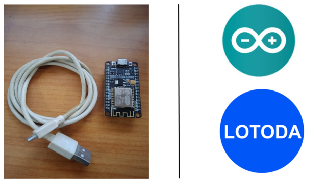
Hardware: 1 Node MCU (ESP8266) và 1 cáp USB, 1 Mạch công tắc Relay 1 Kênh
Software: Arduino IDE và LOTODA app
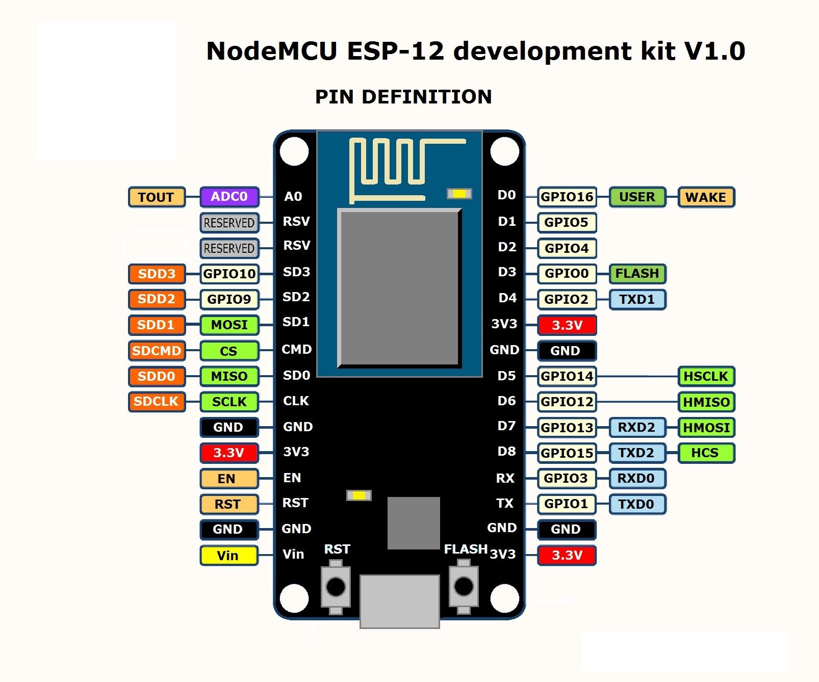
Sơ đồ kết nối từ NodeMCU ESP8266 như sau:
- Pin GND (connecting to DC+ Relay)
- Pin 3V3 (connecting to DC- Relay)
- Pin D1 (GPIO 05) (output to control IN Relay)
Bước 2: Dùng Arduino IDE để nạp code cho NodeMCU
Hướng dẫn nạp code sau đây để bật tắc công tắc và LED built-in trên NodeMCU và kết nối với LOTODA platform. Code như sau:
Chú ý như sau đây trước khi nạp code:
- Bạn cần thay đổi SSID và Password của WiFi mà bạn muốn thiết bị kết nối đến.
- Bạn cần thay đổi DeviceID của thiết bị
- Bạn cần nhập các <User ID Key> và <Password ID Key> của riêng bạn (đã được gởi qua email lúc đăng ký)
-------------------------------------Code start here------------------------------------------------------------
// This example shows how to connect to LOTODA using an ESP8266 and send/receive sample data.
// Make sure you install the ESP8266 Board Package via the Arduino IDE Board Manager and select the correct ESP8266 board before compiling.
#include <PubSubClient.h>
#include <ESP8266WiFi.h>
#define WIFI_SSID "XXXXXXX" //Enter your WIFI SSID
#define WIFI_PASSWORD "XXXXXXX" //Enter your WiFi password
char LotodaServer[] = "app.lotoda.vn"; //app.lotoda.vn is the default servername
int LotodaPort = 1883; //1883 is the default port
char deviceId[] = "LotodaEsp8266-xxxx"; //every device should have a different name
char topic[] = "<User_ID_Key>/lamp/power"; //Enter <User_ID_Key> from LOTODA system, the topic should be different for each device as well
//Please create this new topic on LOTODA mobile app, in this case is "lamp/power"
char User_ID_Key[] = "<User_ID_Key>"; //Enter <User_ID_Key> from LOTODA system
char Password_ID_Key[] = "<Password_ID_Key>"; //Enter <Password_ID_Key> from LOTODA system
WiFiClientwifiClient;
PubSubClient client(wifiClient);
long lastMsg = 0;
char msg[50];
int value = 0;
void setup() {
pinMode(BUILTIN_LED, OUTPUT); // Initialize the BUILTIN_LED pin as an output led
pinMode(5, OUTPUT);
Serial.begin(115200);
delay(20);
Serial.println("Let' start now");
}
void loop() {
if ( !client.connected() ) {
connect();
}
client.loop();
}
void callback(char* topic, byte* payload, unsigned int length) {
// handle message arrived
Serial.print("Message arrived [");
Serial.print(topic);
Serial.print("] ");
for (int i = 0; i< length; i++) {
Serial.print((char)payload[i]);
}
Serial.println();
// Switch on the LED if an 1 was received as first character
if ((char)payload[0] == '1') {
digitalWrite(BUILTIN_LED, LOW); // Turn the LED on (Note that LOW is the voltage level
// but actually the LED is on; this is because
// it is active low on the ESP-01)
digitalWrite(5, HIGH);
} else if ((char)payload[0] == '0') {
digitalWrite(BUILTIN_LED, HIGH); // Turn the LED off by making the voltage HIGH
digitalWrite(5, LOW);
}
}
void connect() {
while (!client.connected()) {
if ( WiFi.status() != WL_CONNECTED) { //replaced by WiFi.status()
WiFi.begin(WIFI_SSID, WIFI_PASSWORD);
while (WiFi.status() != WL_CONNECTED) {
delay(500);
Serial.print(".");
}
Serial.print("Connected to ");
Serial.println(WIFI_SSID);
}
client.setServer(LotodaServer, LotodaPort);
client.setCallback(callback);
if (client.connect(deviceId, User_ID_Key, Password_ID_Key)) {
client.subscribe(topic);
Serial.println("Connected to LOTODA's Server");
} else {
Serial.print("[FAILED] [ rc = ");
Serial.print(client.state() );
Serial.println(" : retrying in 5 seconds]");
delay(5000);
}
}
}
--------------------------------------------Code end here-------------------------------------------------------
Bước 3: Mở LOTODA Mobile app và thiết lập thông số kết nối điều khiển NodeMCU
- Vào menu "SETTINGS", và thêm topic như sau "lamp/power" (chú ý mặc định ứng dụng LOTODA mobile app đã chèn thêm <User ID key> vào phía trước topic bạn tạo)
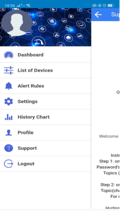
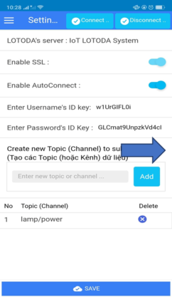
- Sau đó click "Connect ..." để kết nối ứng dụng với IoT LOTODA. Hiển thị trạng thái "Connected" khi bạn đã kết nối thành công.
Bước 4: Tạo khối điều khiển (Widget) trên LOTODA mobile app để điều khiển ON/OFF
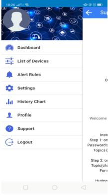
- Vào menu "DASHBOARD" như sau:
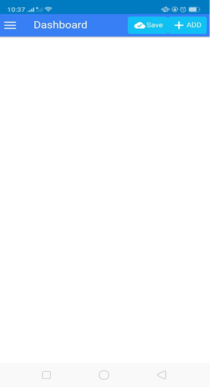
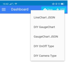
- Sau đó click lên "+ADD" chọn khối điều khiển "DIY OnOff Type" như hình bên dưới.
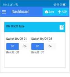
- Tiếp theo click lên icon edit của khối Widget vừa thêm và chọn Topic bạn vừa tạo như hình sau đây.
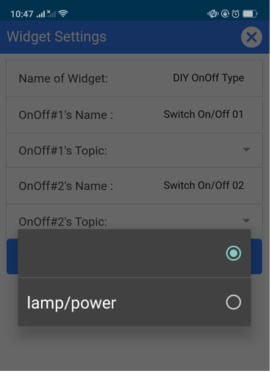
- Sau đó Submit để kết thúc thiết lập.
Đến đây bạn có thể dùng LOTODA mobile app trên điện thoại smartphone để điều khiển Relay 1 Kênh và bật LED trên thiết bị NodeMCU.
Bạn xem thêm chi tiết tại LOTODA Github như sau:
https://github.com/lotoda/Lotoda-Mqtt-Esp
- Chi tiết code để nạp vào Node MCU ESP8266.
- Sơ đồ đấu nối.
Chúc bạn thành công!
Danh sách tin tức
Không có tin tức thuộc chủ đề này
MENU SẢN PHẨM
SẢN PHẨM ĐẶC BIỆT
Không có sản phẩm thuộc chủ đề này.
TIN TỨC HOT

LOTODA – Giải pháp Ứng dụng LOTODA Camera AI Edge Device tích hợp IoT trong lĩnh vực sản xuất và dịch vụ trong nhà máy

LOTODA – Giới Thiệu Kênh Youtube LOTODA - Giới thiệu hướng dẫn sản phẩm LOTODA
![LOTODA – Giới Thiệu IoT LOTODA Brochure [Download]](https://shop.lotoda.vn/datafiles/20824/upload/thumb_images/Bai Viet LOTODA/unnamed.jpg)
LOTODA – Giới Thiệu IoT LOTODA Brochure [Download]

LOTODA – Giải Pháp IoT LOTODA Giám sát hiệu suất trạm làm việc trong sản xuất và nhà máy - Smart Worker
